Bottleneck
The machine group in a factory that has the highest loading for a given product mix. Some authors define bottleneck as having a loading of 100%. However, in common use, bottleneck usually refers to the most highly loaded machine group.
Capacity
The maximum throughput of a factory or workstation. For a factory, the capacity is the throughput rate that drives the idle time on the bottleneck to zero.
Cycle Time
The total time required to produce a product, from entering the factory to leaving the factory. Cycle time includes time actually spent processing, as well as transport time and time spent waiting in queue. Cycle times by operation are also sometimes reported, and include the time from arrival at the operation until completion of processing.
Cycle-Time-Constrained Capacity
The throughput rate for a factory at which the average cycle time is equal to some target amount, usually expressed as a multiple of the total weighted average raw process time of the factory. For example, the 3X cycle-time-constrained capacity is the throughput rate at which the weighted average cycle time for the factory is no more than three times the weighted average raw processing time.
Little’s Law
A fundamental relationship derived by J. D. C. Little concerning cycle time, work-in-process and throughput. Little’s Law states that at a given WIP level, the ratio of WIP to cycle time equals throughput. An illustration is available as part of this tutorial.
Throughput
The average output rate of a factory or workstation. The throughput of a factory is equal to the factory start rate multiplied by average line yield.
Work-in-Process (WIP)
The average number of units of product in the factory (or at a workstation). WIP includes units being processed on equipment, as well as units in transit, or awaiting processing at an equipment group.
The relationship between cycle time and WIP was first documented in 1961 by J. D. C. Little. Little’s Law states that at a given WIP level, the ratio of WIP to cycle time equals throughput, as shown in the formulas below:
In other words, for a factory with constant throughput, WIP and cycle time are proportional. If throughput is held constant, it is impossible to reduce average WIP without reducing average cycle time, and vice versa. It is important to understand that this is a known mathematical relationship. Over the long term, it will hold true for an entire factory or for a single workstation (as long as the units used for each term are consistent with one another).
Little’s Law can be illustrated with a simple example: assume a factory with a capacity of 500 wafers per week and no variability. Although this is a highly unrealistic assumption, we will relax it later in the tutorial. Under these assumptions, if we start 500 wafers or less in each week, the cycle time for each will be one week (because we have enough capacity to process them all during the week).
However, suppose that we start out with a backlog of 500 wafers in the fab. Each week we get 500 more in, so that the total WIP is 1000. We can only process 500 of the wafers in a given week. On average, each wafer will spend two weeks in the factory (one week waiting for the backlog of other wafers to be processed, the next week being processed). Similarly, if we have 1500 wafers in the factory at a time, the average cycle time will be three weeks, etc. This is shown in the graph below.
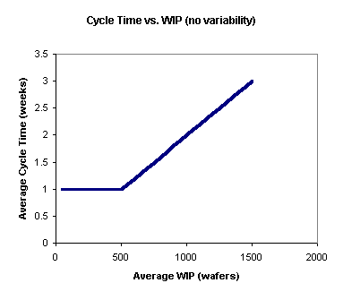
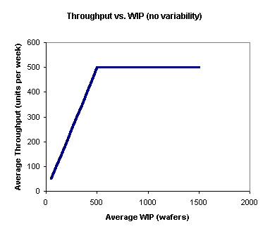
As another way of looking at this, the following graph shows average throughput vs. average WIP. Up to the capacity of the factory, the throughput (the amount we get out per week) will equal the amount that we start per week. However, when the WIP in the factory reaches the capacity of 500 wafers per week, throughput can no longer increase. No matter how much WIP we cram into this factory, we will never get more than 500 wafers per week out (without increasing the fab capacity in some way). And, as shown in the first chart, the more WIP we cram in, the longer the average cycle time will be.
In this example, the best thing to do is clear - start exactly 500 wafers each week. This will maximize throughput, while cycle time remains at the minimum of one week. However, the situation is only this black and white for systems with no variability. For fabs that operate in the real world, we have to consider the relationship between cycle time and variability.
In the (imaginary) no-variability case, cycle time remains constant as start rate is increased, up to the maximum system capacity. At that point, if start rate is increased further, cycle time increases linearly. This is shown in the following chart.

In a real fab, with variability, cycle time tends to increase with start rate (or throughput rate - the two measures are directly related by line yield). Exactly how much the cycle time increases will depend on the amount of variability in the system. In most fabs, once the system is loaded above approximately 85%, cycle time starts to increase rapidly. This is sometimes called the "hockey stick effect," as illustrated below.
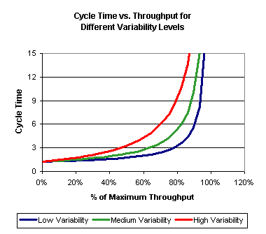
Cycle time limits the effective capacity of a wafer fab. Even the low variability system cannot be run at 100% of the maximum throughput, because cycle time increases rapidly to unacceptable levels. In fact, the limiting case for systems with any variability is that as the factory loading approaches 100%, the cycle time approaches infinity. In the real world, factory planners account for this by including “catch-up capacity” in their plans. That is, they typically plan for about 15% idle time on all of their tool groups. This keeps factories out of the steep portion of the curve shown above.
We have worked on projects in which the factory performance measure used was cycle-time-constrained capacity. This is defined as the maximum capacity at which the factory can achieve a given average cycle time, expressed as a multiple of raw process time. The multiple of raw process time is usually called an X-factor. So, the shorthand term for three times raw process time is 3X. In the chart above, the 3X cycle-time-constrained capacity (or 3X capacity) for the low variability system is approximately 80% of the maximum theoretical capacity of the system. For the highest variability factory, the 3X capacity is only about 45% of the maximum theoretical capacity.
The maximum theoretical capacity of a factory is the start rate that drives the bottleneck to 100% loading. The only way to increase it is to add equipment, or make process changes that reduce the load on the bottleneck. However, as the example chart shows, cycle-time-constrained capacity can sometimes be dramatically improved by reducing variability in the factory. This is one of the key strategies used for low-cost cycle time reduction efforts.
Cycle time increases with variability. For example, suppose that you have a single machine that can process four lots per hour (one at a time). If each lot takes exactly 15 minutes to process, and lots arrive exactly every 15 minutes, then the lots will experience no queue delay. The cycle time through this step for each lot will be 15 minutes of pure process time, and the machine will operate with 100% utilization. However, in a real fab, neither the interarrival times nor the processing times will be exactly the same from lot to lot.
Variability in Processing Times
All sorts of things contribute to variability in processing time in a fab. Different recipes are processed on the same machine, and have different process times. Setups increase process time (from the lot’ perspective), as do equipment failures. When rework lots come through, they typically have fewer wafers than regular lots, and so have lower processing times. Similarly, yield loss reduces the number of wafers per lot, and can reduce process time per lot. Operators don’t always remove lots from the machine immediately upon completion, increasing the effective process time.
Suppose that in the example above the processing time averages 15 minutes, but can range from 10 minutes to 20 minutes for each individual lot. Also suppose that the first lot takes 20 minutes. When the second lot arrives 15 minutes after the first, it will have to wait for five minutes. This means that the average queue time of the first two lots has increased from zero to 2.5 minutes. And things will just keep getting worse over time. Once you have any lots that wait, you can never again have zero wait time, because the best case for a lot is that its waiting time is zero. You never have any negatives to cancel out the positive delay.
Now suppose that the first lot only took 10 minutes to process. This means that the machine will be idle for five minutes, until the second lot arrives. This is a problem, because this machine is supposed to be operating at 100% utilization. Those five minutes of idle time can never be recovered. For a good illustration of this, we recommend that you read The Goal by Eli Goldratt and Jeff Cox.
Variability in Arrival Times
Even more of a problem in wafer fabs than variability in process times is variability in time between arrivals. The primary culprit here is batch processing. Suppose that in our example, the step before the example machine takes place on a batch tool with a batch size of four lots, and a processing time of one hour per batch. Instead of arriving at our machine once every 15 minutes, lots arrive instead in a batch of four every hour. Since the example machine can only process one lot at a time, the other three lots will have to wait while the first lot is processed. Then lots three and four will wait while the second is processed, and so on. The average queue delay for this batch (assuming that the machine is idle when it arrives) is [0 + 15 + 2*(15) + 3(15)]/4 = 22.5 minutes.
Other factors also contribute to variability in lot arrival times, including rework, transfer batching, and operator delays. The net result is that when a system has variability, the cycle time increases. How much the cycle time increases depends in part on the utilization of the system. In the example below, we have a single machine, loaded to 60%, 75%, and 90% utilization. The process time is constant, but the interarrival times vary. As the chart shows, the more variability there is in the arrival process (as shown on the X-axis), the higher the cycle times will be (as shown on the Y-axis). The higher the overall utilization of the system, the worse the effect is.
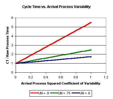
The above chart was generated using a simple queueing formula for the queue delay for a single machine. Simulation can also be used to do what-if analysis of the impact of variability on cycle time. The bottom line is that any system with variability will experience some queueing; the higher the utilization of the system, the worse the effect. See the discussion on cycle time and capacity above for more details.
Background
Batch tools are tools in which more than one lot may be processed at one time. They are generally used for very long operations, such as furnace bake operations. For example, a typical batch furnace might be able to process up to eight lots at one time, and have a process time of up to twelve hours. Processing time is usually independent of the number of lots in a batch, and once a batch process begins, it cannot be interrupted to allow other lots to join.
From a local perspective, when a furnace is available and full loads are waiting, the decision to process a batch is obvious, since no advantage can be gained at that work area by waiting (although a decision may still be needed concerning which product type to process). However, when there is a furnace available and only partial loads of products are waiting, a decision must be made to either start a (partial) batch or wait for more products to arrive.
There are two problems with running a partial batch. One is that the unused capacity of the furnace will be “wasted.” The other problem is that lots that arrive immediately after the batch starts cannot be added to the batch, and might have to wait many hours until another furnace is available. There are also problems that stem from waiting to form a full batch. The lots that are waiting to be processed incur extra queue time while waiting for other lots to arrive. The furnace is held idle, driving down its efficiency. And full batches contribute more to variability after the furnace operation.
Batch Size Decision Policies
There are two basic types of batch size decision policies. The first type are known as Minimum Batch Size (MBS) decision rules, or threshold policies. An MBS rule simply states that, whenever there are N lots in queue, ready to form a batch, and a furnace is available, immediately start processing those N lots. Here N could be any value from one up to the maximum load size for the furnace. An MBS rule with a load size of one is sometimes referred to as a greedy policy, while one with the maximum load size is called a “force-full” policy (since the furnace is only run when it is as full as possible). The other category of batch size decision rules are known as “look-ahead” rules. With a look-ahead rule, the furnace operator looks ahead in some way to see which lots are expected to arrive soon, and sometimes waits to form the batch until additional lots arrive. Different methodologies are used to decide when to wait, but the general idea is to minimize the sum of the expected waiting time for lots already in queue and lots expected to arrive within some time window. Look-ahead policies are naturally dependent on the accuracy of the information concerning future arrivals, and require the presence of some sort of predictive control system. For the remainder of this article, we will focus on threshold policies, rather than look-ahead policies.
Single-Tool Results
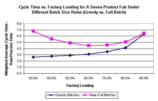
Suppose we have a single furnace, that can process up to eight lots at one time, and has an eight-hour process time (constant) and exponential interarrival times. We ran a series of discrete-event simulation replications in which we varied the interarrival time, in order to vary the utilization of the furnace from 20% to 95%. We ran two sets of experiments, one with a greedy batching rule, and the other with a full-batch rule (always wait to form full batches). The results are displayed in the graph below:
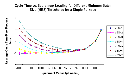
Here we see that until the furnace is loaded to about 90%, a greedy (minimum batch size of one) policy results in lower cycle times than a full-batch policy. At high utilizations there is a very slight improvement from using a full-batch policy over a greedy policy.
Full Factory Model Results
You might wonder if this has any effect on the factory as a whole. After all, an extra few hours here or there on the furnaces could be lost in the noise relative to the overall cycle time. We therefore did another experiment using a simplified version of a full factory model. The model had two products, 115 steps per process flow, 22 tool groups, and 21 operator groups. We simulated this model for two years, varying the start rate to allow different levels of bottleneck utilization for each run, and obtained the following results:
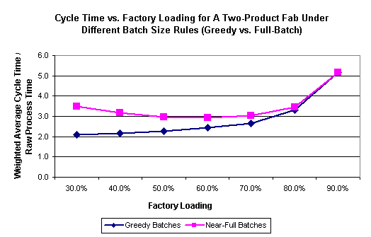
In the full factory model, the average cycle time is almost 70% greater for the full-batch policy than for the greedy policy at very low utilizations. Up to 80% loading, the greedy batch policy yields lower cycle times. For very highly loaded fabs the full-batch policy yields essentially the same results as the greedy policy.
For a more extreme example of the impact of batching on this fab, we modified the factory to have a greater number of products. We held the total volume the same, but divided it among seven products instead of two. All products used the same process flow, but for certain batch tools in the model, lots of different product types could not be batched together. This change thus increased the volume of distinct batch IDs in the model. The change led to a slight degradation in performance under the greedy policy, and to a significant cycle time increase under a full-batch policy, as shown below:
Clearly, batching policy makes a big difference in this high-product mix fab because there are so many distinct batch IDs. Lots almost always wait a long time to form a batch under a full-batch policy, especially for very low utilizations. The increase in cycle time between this case and the previous case also illustrates how sensitive fab models can be to batching rules (in this case, decisions about which types of lots can be batched together).
In conclusion, for batch tools that are not highly loaded, setting a high threshold for a minimum batch size decision rule (forcing full or near-full batches) can significantly increase local cycle times, as well as overall fab cycle times.
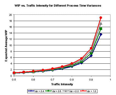
The Pollaczek-Khintchine (called P-K, for obvious reasons) formula gives the expected average WIP at a single-tool workstation where arrivals to the workstation are highly variable, and process times are somewhat less variable. More specifically, the formula applies when interarrival times to the workstation are exponentially distributed, and process times follow a general distribution (M/G/1 queues). For tools that fit this description, the expected WIP can be computed from the mean interarrival time, the mean process time, and the variance of the process time distribution.
It turns out that in a wafer fab, interarrival times to a given workstation usually are highly variable, and some research does suggest modeling them as exponential. We usually think of process times as being fairly constant. However, if you look at process time as the time from when a lot gets to the front of the queue to when it finishes processing, then things like setups, equipment downtimes, operator delays, and different operations processed on the same tool all add variability to the process times as seen by successive lots. And this variability, as shown by the P-K formula below, can drive up WIP and cycle time.
WIP = average number in queue and in process (units)
λ = arrival rate (units per hour)
μ = service rate (units per hour)
ρ = l /m (traffic intensity or utilization)
σ2 = variance of service time distribution (0 for constant service times)
WIP = {ρ} + {[ρ2]/[2*(1 - ρ)]} + {[λ2*σ2]/[2*(1 - ρ)]}.
If you look at the above formula for WIP, you see that it is first of all a function of traffic intensity. We know this. As a tool is loaded more heavily, the number of wafers in queue increases. As ρ approaches one, the denominator of the last two terms approaches zero, and the WIP approaches infinity. This is why capacity planners always plan for a capacity buffer on each tool group - to keep the WIP from becoming very large. You’ll also notice in the P-K formula as stated above, that the last two terms in curly brackets have the same denominator, and could be combined. We separated them to highlight the influence of process time variability. If you have constant process times, the whole last term drops off. If you have highly variable process times, that term can become significant. A graph illustrating this is shown below:
The graph shows that it is mostly equipment loading that drives cycle time at individual tools. If we just care about reducing cycle time, we can decrease start rates or increase capacity, and cycle times will go down. However, either of these approaches costs money. The nice thing about variability reduction is that it also reduces cycle time, without requiring costly equipment purchases or decreased start rates.
What the P-K formula tells us is that, if we look at individual tools in the fab, anything that we can do to reduce variability in the process times seen by successive lots will directly act to reduce WIP at these tools, without requiring any reduction in tool loading. And, as predicted by Little’s Law, cycle time will go down at the same time. The P-K formula is the mathematical justification for variability reduction efforts in a wafer fab.
For a derivation of the P-K formula, see Fundamentals of Queueing Theory: Second Edition, by Donald Gross and Carl Harris (Wiley), page 254-256.